Le projet de recherche est issu d’une expérimentation à l’aide d’instruments de relevés inventés à la Renaissance. Il s’agit d’une suite logique des exercices sur la mesure et la cartographie effectuées dans le cadre de ce cours.
La plupart des instruments de mesures des arpenteurs de l’époque dépendent d’artifices mathématiques dont certains ont été résumés dans l’œuvre de Leon Battista Alberti, Ludi Mathematica. Dans cet ouvrage, il explique diverses astuces mathématiques relatives à l’art de la mesure. Suite à la reproduction de la carte de Rome d’Alberti en deuxième exercice, nous avons défini deux points d’intérêts pour le projet final : la numérisation des points du relevés d’Alberti est indépendante du support sur lequel le relevé a été fait; il est possible pour n’importe qui de reproduire cette carte peu importe sa taille, pourvu que l’instrument qu’il décrit soit reproduit consciencieusement. L’élément fascinant est que sans le savoir, Alberti utilisait un système d’analyse computationnel peu différent que le langage d’un ordinateur moderne. Deuxièmement, l’instrument utilisé par Alberti pour construire sa carte démontre à notre avis l’introduction d’un système de coordonnées polaires appliquées dans l’art de la mesure. Ce système allait définir le point de départ du projet.
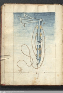
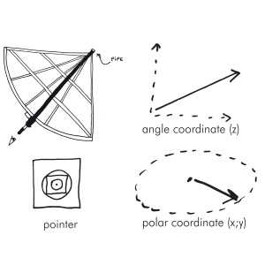
Le projet est né d’une recherche approfondie sur les divers instruments de mesure inventés par Alberti. Nous avons consulté tout d’abord les Ludi Mathematica afin de comprendre comment Alberti avait transposé les éléments remarquables de Rome en nuage de points mathématiques. Il s’avère qu’Alberti utilisait un instrument circulaire de grande dimension déposé sur le sol permettant d’établir à vue les angles des points d’intérêts par rapport au lieu de mesure. Au cours de nos recherches, nous avons lu attentivement le traité De Statua, où Alberti décrit un deuxième instrument de mesure inspiré du premier permettant de mesurer une statue. Alberti donne un système de proportion à son instrument dans la mesure où la hauteur de la statue est égale à 6 pieds. Il présente ensuite l’instrument de mesure, le finitorium. Il s’agit d’un instrument semblable à celui utilisé pour la carte de Rome, excepté qu’il implique maintenant une composante tridimensionnelle à son fonctionnement en la qualité d’un fil à plomb suspendu à son rayon. Ce dernier est de 3 pieds, chacun divisés en 10 uncia et subdivisées en minuta.
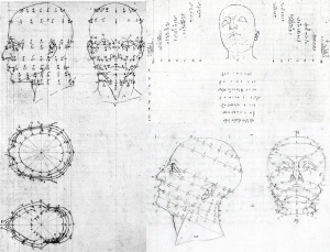
En utilisant l’instrument décrit par Alberti, de manière très imprécise disons-le, on comprend qu’il serait possible de diviser le contour de n’importe quel objet en coordonnées spatiales, qu’il serait ensuite possible de retracer sans la présence de l’objet de référence. Nous avons fait d’autres recherches à comprendre exactement le fonctionnement de cet instrument. Nous avons établi que sa reproduction exacte n’avait à notre connaissance jamais été tentée. Mathématiquement, ce sytème repose sur les coordonnées cylindriques où un point dans l’espace est défini par le rayon, l’angle dans le plan horizontal et z, la distance verticale. D’autre part, il s’avère que le principe d’Alberti a été effectivement utilisé par les sculpteurs afin de reproduire des statues. Le principe est le suivant : le sculpteur positionne deux ou trois points de référence majeurs (le coude, le genou, etc) par rapport au centre de l’axe vertical et sait ainsi la position de chaque point par rapport à l’épaisseur du bloc de matériel à tailler.
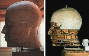
Le projet final se veut une hybridation des différents principes de mesure inventés par Alberti. Nous avons voulu modifier l’instrument afin de le rendre capable de mesurer n’importe quel objet. Le résultat final est une « boîte de duplication », où un objet peut être inséré, mesuré, transformé en une série de coordonnées tridimensionnelles, et par la suite reproduit. Plus le nombre de points mesurés au départ a été grand, plus la reproduction de l’objet sera précise.
Le définisseur mesure 30 cm de diamètre et la hauteur de la boîte mesure 24 cm, soit 80% du rayon de mesure. On pourrait étendre ce système de proportion à volonté, en multipliant ces mesures du facteurs de notre choix, afin de mesurer un objet plus gros.
La première étape est donc d’insérer un objet dans la boîte et d’utiliser la plaque de mesure afin de noter une série de points judicieux en terme de rayon, d’angle et de distance z. Par la suite, si on imagine ne posséder que cette série de coordonnées, il est possible de reproduire le contour de l’objet à l’aide d’une seconde plaque contenant un tableau de coordonnées polaires. On suspend alors chaque point sur cette plaque à l’aide d’un fil à plomb. Le nuage de points qui en résulte reprend alors le contour de l’objet mesuré au départ.
Finalement, nous avons souhaité expérimenter avec la notion de projection, de vision et de parallaxe en tentant d’introduire une grille de mesure sur les faces latérales de la boîte. Nous espérions pouvoir obtenir une projection parallèle du contour de l’objet une fois les points suspendus dans l’espace. Cette méthode aurait alors pu fournir l’élévation de des contours de l’objet mesuré.
***
The research project is the result of an experiment using surveying instruments invented in the Renaissance. It is a logical step forward from previous exercises on measuring and mapping.
Most instruments surveyors used at the time depend on mathematical artifices. Some of them were summarized in the work of Leon Battista Alberti, Ludi Mathematica. In this treatise, he explains various mathematical tricks on the art of measurement. Following the reproduction of the map of Rome as a second exercise for this class, we identified tree points of interest for the final project:
– Alberti’s surveys coordinates are independent of the medium on which the map has to be drawn. It is possible for anyone to reproduce this map in any size, assuming Alberti’s instrument is conscientiously reproduced.
– The other fascinating element is that without knowing it, Alberti used a computational analysis system which is in our opinion not much different than the language of a modern computer.
– Finally, the instrument used by Alberti to build his map introduces the notion of polar coordinate system applied in the art of measurement. This system defined the starting point of the project.
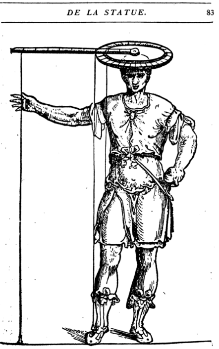
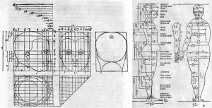
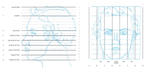
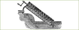
Alberti’s Finitorium, as pictured in De Statua treatise.
The project originated from extensive research on various measuring instruments invented by Alberti. We first consulted the Ludi Mathematica treatise to understand how Alberti had transposed the remarkable features of his Rome map into a discrete mathematical array of points. It turns out that Alberti used a large circular instrument placed on the ground in order to establish the angles of points of interest in relation to his location on site (For the Map of Rome, the zero coordinate was the summit of Capitola). During our research, we then examined Alberti’s De Statua, where Alberti describes a second measuring instrument used to survey a standing statue. Alberti confers a proportion system into his instrument by defining that the height of the statue to be measured is to be “6 feet” tall. It then presents the measuring instrument itself, which is called the finitorium. It is an instrument similar to the one used for the map of Rome, except that it now involves a component for its operation in a three-dimensional space. The added component is a plumb line suspended from the radius of the instrument. The radius is 3 feet, each divided into 10 uncia and subdivided into minuta. By using this defined proportional system, one’s can enlarge or reduce the instrument according to the height of the statue to be measured.
By replicating the instrument described by Alberti, we can understand that it would be possible to divide the outline of any object into spatial coordinates. Having these coordinates at hand, it would also be possible to replicate its outline without the presence of the reference object. Some other research was done in order to understand exactly how this instrument could work in a practical way. To our knowledge, an exact replication of the finitorium instrument has never been attempted. Mathematically, this point-by-point survey of a body is based on cylindrical coordinates, where any point in space is defined by it’s radius, it’s angle in the horizontal plane, and z it’s vertical distance from the horizontal plane where the radius sits. On the other hand, it turns out that the measurement principle invented by Alberti was actually picked up by sculptors to reproduce statues. The principle is as follow: the sculptor positioned two or three major reference points (elbow, knee, etc.) from the center of the vertical axis and thus could know the position of each point relative to the thickness of the material to be cut.
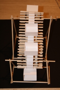
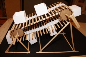
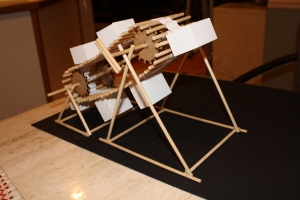
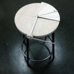
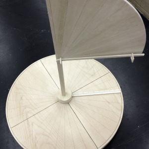
The final project is intended to be an hybridization of these different measurement principles invented by Alberti. We wanted to change the above instrument to make it able to measure any object. The end result is a “replication box”, where an object may be inserted, measured, converted into a series of three-dimensional coordinates, and then reproduced. The greater the number of points is measured, the greater the resolution of the reproduced object will be.
The Finitorium measures 30 cm in diameter and the height of the box is 24 cm, or 80% of the radius span. In order to measure a larger object, this proportion system can be easily extended. One’s only need to multiply these dimensions by a given factor of choice.
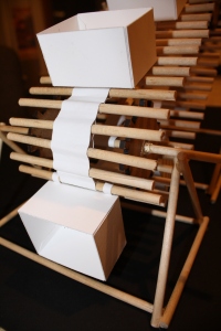
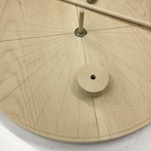
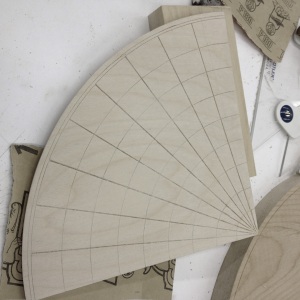
The first step is to insert an object into the box and use the measuring plate to compute a succession of wisely chosen points in terms of radius, angle and z distance. Subsequently, it is possible to reproduce the contour of the object with a second plate containing a polar array. Each point is to be suspended from the plate with a plumb line, with correct z distance. The resulting points cloud will approximate the contour of the object.
Finally, I wanted to experiment with the concept of projection and vision, by trying to introduce a measurement grid on the sides of the box. That way, I was hoping to catch a parallel projection of the object’s contour points, once being suspended in space. This method could then provide key elevation contour points of the measured object.

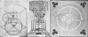
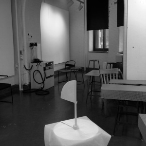
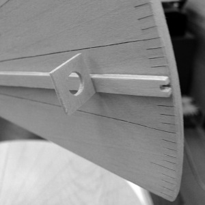
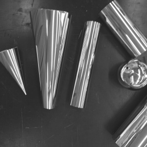
Alberti’s Finitorium replicated following his instructions.

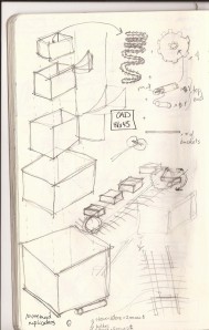
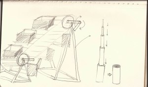
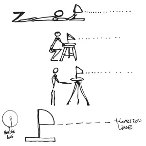
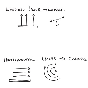
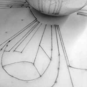
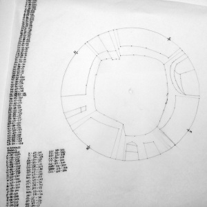
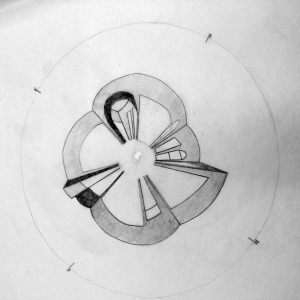
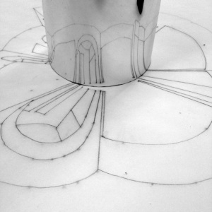
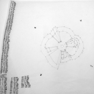
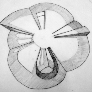
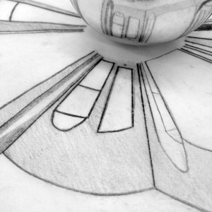
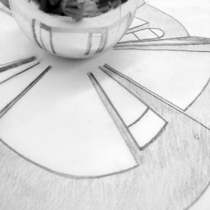
Preliminary sketch of the instrument

Preliminary sketch of the instrument

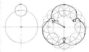
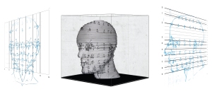
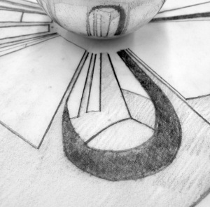
Experimental set of cylindrical coordinates.

Computer generated plot of measured points for validation purposes.

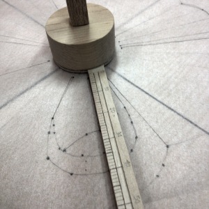
Step 1: Measurement of a point following Alberti’s method.

Step 1: Measurement of a point following Alberti’s method.

Step 1: Measurement of a point following Alberti’s method.

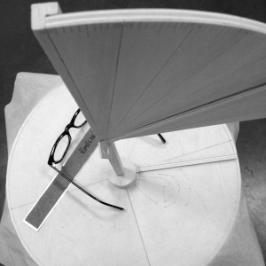
Step 2: reconstruction of the measured coordinates into a model.

Step 2: reconstruction of the measured coordinates into a model.

Step 2: reconstruction of the measured coordinates into a model.

Step 2: reconstruction of the measured coordinates into a model.Measurement of Z coordinates projection using an orthogonal grid.

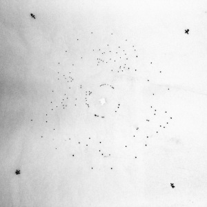
Step 3: validation of the measured points.

Step 3: validation of the measured points.

Step 3: validation of the measured points.
Bibliography
Académie d’Art de Meudon et des Hauts De Seine, Histoire d’une commande imago pietatis Les procédés de reproduction, [online], http://www.academieart-meudon.fr/wdp/wp-content/uploads/2011/10/Texte-rencontre-Agn%C3%A8s-Bracquemond1.pdf
Alberti, Leon Battista. Ex ludis rerum mathematicarum, in Williams, Kim, The Mathematical Works of Leon Battista Alberti, Birkhäuser, Berlin, 2010.
Alberti, Leon Battista, De La Statue et de La Peinture, traduit du Latin en Français par Claudius Popelin, A. Lévy Éditeur, Paris, 1868.
Carpo, Mario, The Alphabet And The Algorithm, MIT Press, Cambridge, 2011, 169p.
Grafton, Anthony, Leon Battista Alberti Master Builder Of The Renaissance, Hill and Wang, New-York, 2000, 417p.
Miller, Naomi, Mapping the City, Continuum, London, 2003, 270p.
Scaglia, Gustina, Instruments Perfected for measurements of man and statues illustrated in Leon
Battista Alberti’s De Statua, Nuncius, Volume 8, Number 2, 1993, pp.555-596.
Williams, Kim, The Mathematical Works of Leon Battista Alberti, Birkhäuser, Berlin, 2010.
")


![vitruvius 2 [Converted]](https://f12arch531project.files.wordpress.com/2012/12/vitruvius-2-converted.jpg?w=108&h=89)
![vitruvius 1 [Converted]](https://f12arch531project.files.wordpress.com/2012/12/vitruvius-1-converted.jpg?w=126&h=75)
![vitruvius 3 [Converted]](https://f12arch531project.files.wordpress.com/2012/12/vitruvius-3-converted.jpg?w=108&h=71)


![According to the Oxford English Dictionary, this is the first use of the word 'volvelle' in English (written in red about 2/3 of the page down), 'ye rewle of the volvelle' [the rule of the volvelle], 15th century. The Bodleian Libraries, The University of Oxford, MS Ashmole 191, f.199r.](https://f12arch531project.files.wordpress.com/2012/11/ms-ashmole-191_f199r1.jpg?w=354&resize=354%2C562&h=562#038;h=562 "Bodleian Library (Oxford), MS Ashmole 191, f.199r")
, MS Savile 100, f.6r")
, MS Savile 100, f.8r")
, MS Ashmole 789, f.363r")
, MS Ashmole 789, f.363v")
, MS Ashmole 789, f.364r")
, MS Ashmole 789, f.364v")
, MS Ashmole 789, f.365r")
, MS Ashmole 789, f.365v")


, plate 3")


, 1918")
, 1918")

, \"Novae theoricae planetarum\" (from the Lawrence J. Schoenberg Collection)")


, f.101r")

, CCA")
, CCA")


")


